GCC - Reverse1
This challenge was created by aiglematth as part of the ctf club GCC. This was my first introduction to the Unicorn framework. The challenge has no real difficulty other than understanding the framework but remains very interesting to study. This post was written with many details for begginers.
Setup
When we try to launch the binary we get the following error:
|
|
To solve the problem, install Unicorn and move libunicorn.so.2 to your shared library folder or load it manually when starting the program.
|
|
To disable ASRL in an unprivileged docker you will have to do it at your host level.
|
|
ASLR protection must be disabled on the host in order to avoid having random addresses for the instructions each time the program is launched
Don’t forget to reactivate it after your analysis by replacing the 0 with a 2
Binary analysis
Main function
The first thing to do once we reach the main function is to rename the variables that you can easily determine.
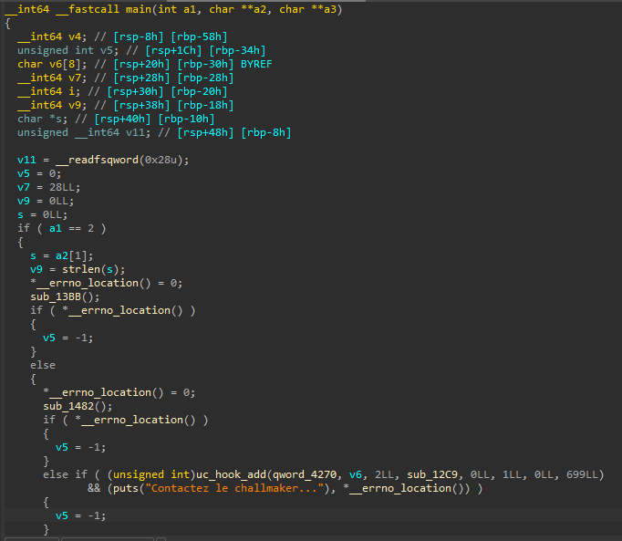
We now have a slightly more readable code. We can already see that it is necessary to give a parameter to the program (probably a password) to obtain the flag. We notice that two internal functions without given symbol are called followed by the same uc_hook_add function called twice with different parameters.
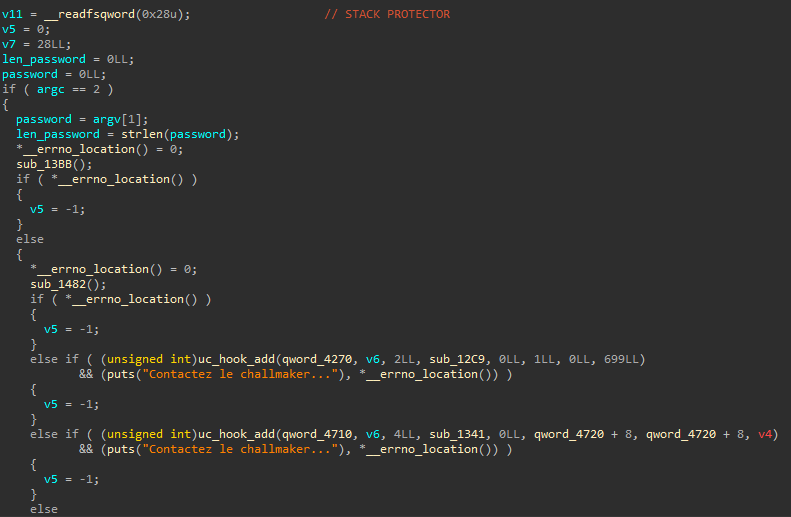
Searching for uc_hook_add on the Internet we find that this is a function of the project Unicorn which allows emulation of multiple CPU architectures. On Hot Examples there are templates to use Unicorn.
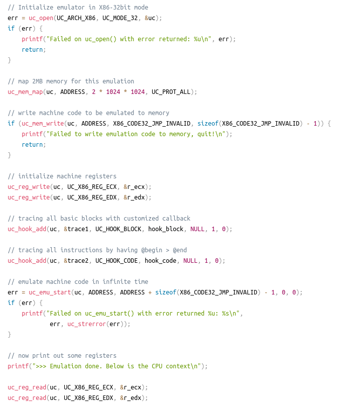
Open function
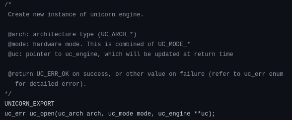
As seen on the image above we should have a call to the uc_open function. By going to the first sub_13BB function, we find this call. In the function there is a loop which will be used to generate 4 Unicorn Engine.
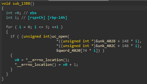
We rename the variables based on their definition in unicorn.h.
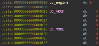
As for parameter values, UC_ARCH is 3, UC_MODE is 4, and the uc_engine is a pointer to a structure that is updated at the function end.
In unicorn.h or in unicorn_const.py, there are enums for the architecture and the mode. We will therefore have a MIPS architecture in 32 bits little endian:
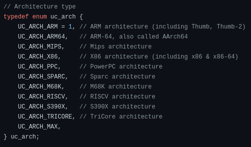
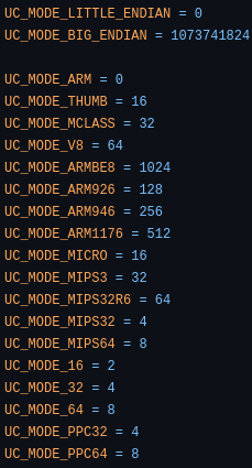
The enums can be copy paste by going into local types (Shift + F1) then press insert and paste. Their is now a new enum inside the enums window.
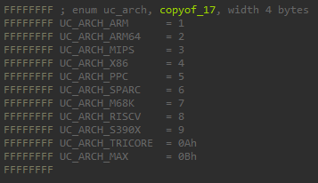
We can replaced the representation of UC_ARCH in the .data section.

When we retrieved the value of the function parameters, we could see that uc_engine was contained on 8 bytes (64 bits) but UC_ARCH and UC_MODE were on 4 bytes (32 bits) each. Moreover, in the disassembled code, edi and esi are used, not rdi or rsi.

In the function menu uc_hook_add is in purple as well as other starting with uc. These functions can be find inside the import table, since their are in the dynamic symbol section IDA can retrieve their symbols. However, IDA don’t have the signature of these function therefore the return type and the parameters type will not be known. IDA will only try to guess them.
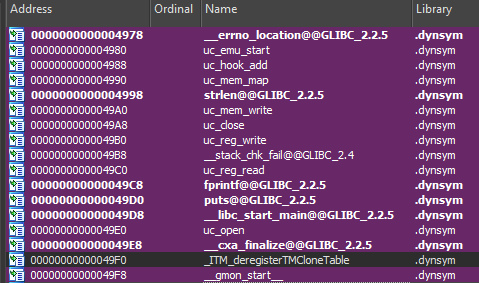
We replace QWORD (64 bits) with DWORD (32 bits) for the first two parameters.

This gives us the following decompiled code:

We can also change the type of UC_ARCH and UC_MODE to __int64 []. Actually, as we ask for 32 bits in input because of the DWORD if there is more bits (for example 64), only the first 32 will be kept. The advantage is that the size of the elements of the table will be identical to uc_engine one (8 bytes). 0x4A is used as offset since our elements as a size of 8 bytes, but for an elements with a size of 1 bytes, we need to multiply by 8 which means 0x4A * 8 = 0x250 here. First, we change type of uc_arch and uc_mode enums to __int64 by changing the width to 8.

Next, we replaced the previous type of UC_ARCH and UC_MODE by uc_arch [].

Now, we get a function that looks like this:
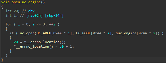
By going 0x250 further we obtain the second uc_engine which corresponds to x86 on 16 bits in little endian with 4 in architecture and 2 in mode:
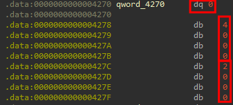
Repeating the operation for the next two rounds of the loop, gives us ARM in little endian then PPC on 32 bits in big endian.
Mem map and write function
Mem map
The next function use uc_mem_map to allocate memory size for the data that we want to put in the emulated CPUs as well as two calls to uc_mem_write to write the data in the memory.
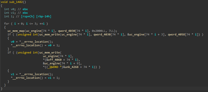
According to the code in unicorn.h, uc_mem_map, the second parameter is the starting address of the memory region to allocate, the third is the size of this memory region and finally the protections for the last parameter. This means that each Unicorn Engine will have an address that starts at 0, a size of 8KB (0x2000) with a permission that is set to 7.
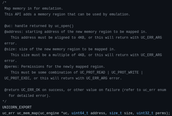
Still looking in unicorn.h, we find an enum for protections with 7 which corresponds to Read, Write and Execute.
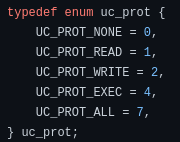
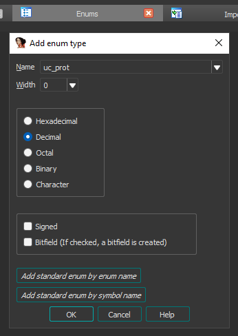
We will create an enum in the menu and add UC_PROT_ALL in it:
Mem write
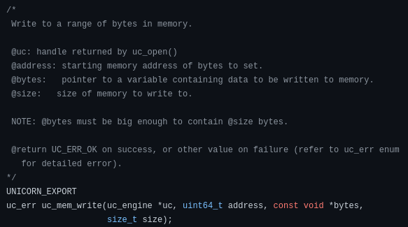
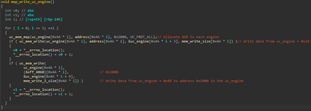
For the uc_mem_write function, on the first call the address will be 0, the data will be taken from uc_engine + 0x18 because 3 * 8 = 0x18 and the size will depend on each Unicorn Engine (between 0x8 and 0xC). On the second uc_mem_write the data will be at uc_engine + 0x48 with a size of 0x1C (or 0x100 for the ARM CPU). The address will be 0x1000.
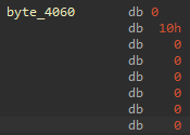
To verify that the address will be 0x1000, we look at the content of off_4060, it is indicated that it’s a QWORD which represents the address of _init_proc.

By changing the type in another format we realize that it is in reality 0x0000000000001000:
The function after all the changes:
Hook function
Addition hook
We can continue with the two uc_hook_add functions. These functions allow you to perform an action when a specific event is received.
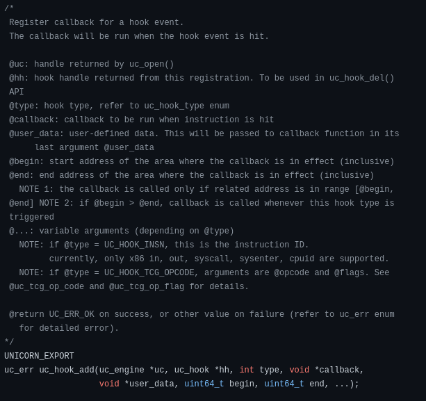
For the first call, the address of the Unicorn Engine used corresponds to the x86 emulated CPU (0x4020 + 0x250 = 0x4270). The type of hook is defined in the third argument (2 here) which is equivalent to UC_HOOK_INSN. It allows to hook a specific instruction. The next argument is the function we are going to perform when the hook is triggered. The last argument is optional, it corresponds to the instruction that we want to hook in our case it will be syscall.

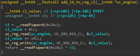
The function that will be performed when there is a syscall instruction in uc_engine_x86 will be sub_12C9. This function will read a register and add 19 to the value read before writing it back to the same register. In x86_const.py, we learn that 10 correspond to the cl register.
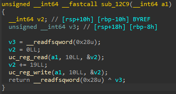
This gives us:
Is equal hook
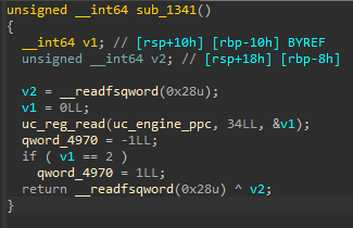
The second call to uc_hook_add, use the Unicorn Engine PPC (0x4020 + 0x250 * 3 = 0x4710), with UC_HOOK_CODE as the hook type. The zone that will be used to trigger the hook corresponds to the beginning of the first data written.

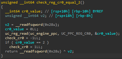
If the hook is triggered, the sub_1341 function will be used. This will read the values of a register and compare it to 2, if it is equal qword_4970 is set to 1 otherwise -1. The register whose value is taken corresponds to cr0.
Looking at the references to qword_4970, we notice that it is used in the main. It subtract a number from v6 (which is equal to 0x1C). We therefore understand that our password length must be 0x1C and that it will be decremented 1 by 1 if the cr0 register is equal to 2.
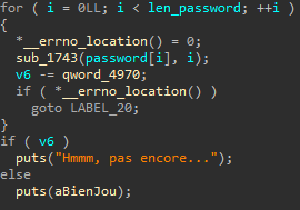
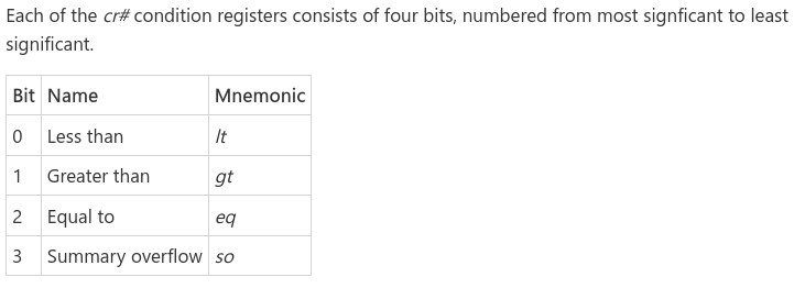
According to Microsoft, if bit 2 of a condition register is set to 1, this means that the two numbers are equal following a comparison. As the bits are from the most significant to the least significant, bit 0 will be worth 8, 1 will be worth 4 and so on for the other bits. Consequently, this means that the equality which is checked is used to indicate whether a comparison operation present in the emulated CPU PPC has returned an equality.
The function now looks like this:
The uc_hook_add functions are also more readable:

Check password function
It only remains to analyze the behavior of the sub_1743 function which takes as a parameter each character that is provided to the program 1 by 1 trough the loop as well as the current index. This function is divided into 4 parts which will globally write into registers, execute each emulated CPUs and then read another register. We’re going to have to do some debugging to get data that is written with uc_mem_write rather than doing it with static IDA.
To get the base address, use starti which is equivalent to putting a breakpoint at 0x0 and running the program. Then execute piebase to get the base address inside pwndbg:
|
|
We can now set breakpoints on calls to uc_mem_write function, by adding the RVA (Relative Virtual Address) of the call with the base address:
|
|
MIPS CPU
Once the breakpoints are positioned, we will launch the binary with a random argument to stop on our first breakpoint.

Inside the mem_write part, the third argument specified was pointer to the data. Here our data is at address 0x555555558038.

After collecting the written data, we disassemble them on shell-storm.org.
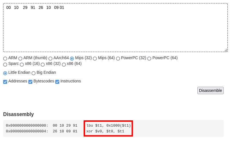
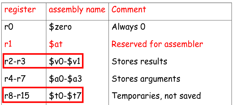
The first instruction will load into $t1, the unsigned byte contained in 0x1000 + $t1. While the second instruction will xor $t0 and $t1 before storing the result inside $v0. According to the MIPS documentation, the r8 register corresponds to $t0, r9 to $t1 and r2 to $v0.
By analyzing the first part, it writes into the register r8/$t0 a character of the password as well as its index in r9/$t1 according to the constants of the file mips_const.py. Then, start the engine which will execute the different instructions written before. Finally, the result of the xor which is in r2 will be stored in return_value.
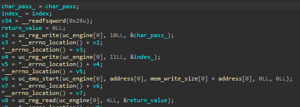
What is loaded into $t1 at the address 0x1000 + index corresponds to the second memory zone where we write. As there is a difference of 0x30 (0x48 - 0x18) between the two uc_mem_write, we can recover the data by adding this difference to the previous address 0x555555558038 + 0x30.

The other possibility is to continue until the next breakpoint.
x86 CPU
To understand how x86 CPU instructions work, we repeat the same actions by retrieving the address where the data is stored:

Disassembled data indicates that the first instruction will move a byte from 0x1000 + eax into cl which will then be added to bl, before a syscall.
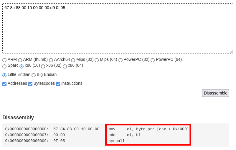
In the second part, the value of return_value is written in the register bl and the index in al (al is contained inside eax). Afterward, we start the engine and get the value of cl.

Again the data at 0x1000 corresponds to the second uc_mem_write.

Do not forget the syscall which is hooked by the first uc_hook_add function, this will add 19 to the value of cl.
ARM CPU
We use the same method for this section, after recovering the data from the first uc_mem_write, we decompile the code.
The instruction will put in r1 the value which is steored in the current address plus 8 bytes which is 0x00001000 (corresponding to the address of our data of the second uc_mem_write). Then, we will retrieve the byte pointed by the address of r1 (0x1000) plus r0. The last instruction is not useful, the purpose was just to provide 0x1000 as data.
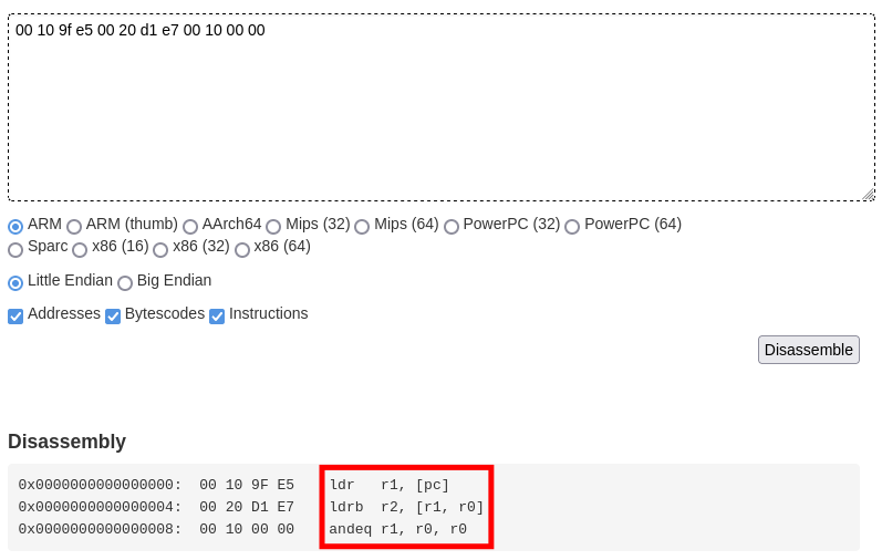
In the third part, the value of return_value is written to the r0 register. next, the engine is started and put the value of the r2 register in return_value. This indicates that this emulated CPU will simply retrieve the value of the byte pointed by the value of return_value.

This time there will be 0x100 bytes to have all bytes from 0x00 to 0xff referenced.

PPC CPU
As it is big endian after having recovered the data of the first uc_mem_write, we will change the endianness every four bytes because we are in 32 bits.

By decompiling, we can see that the first lbz instruction retrieves the value of 0x1000 + r1 and places it in r1. Then, we have a comparison operation between r0 and r1 which store the result in cr0, if the two operands are equal cr0 will be worth 2 as we saw with the PPC hook.
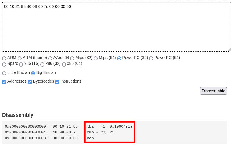
According to the code it is the value of return_value which will be placed in r0 and the index in r1.

Solving script
After getting all the data from the second uc_mem_write for the different parts. We loop from 0 to the length of the password (0x1C). In this loop we will search for the index in offset_data corresponding to the value of the array enc_flag. Then, we remove the value of add_data[i] from the index. We subtract 19 before doing a modulo 256 to not exceed 0xFF. Finally, we xor with xor_data[i].
|
|
Flag
Flag : GCC{tu_as_pris_du_plaisir??}